The Process of Drawing Architectural Plans
Architectural Plans Tutorial - How I Describe Floor Plans
Want to meet all of my tools + gear?
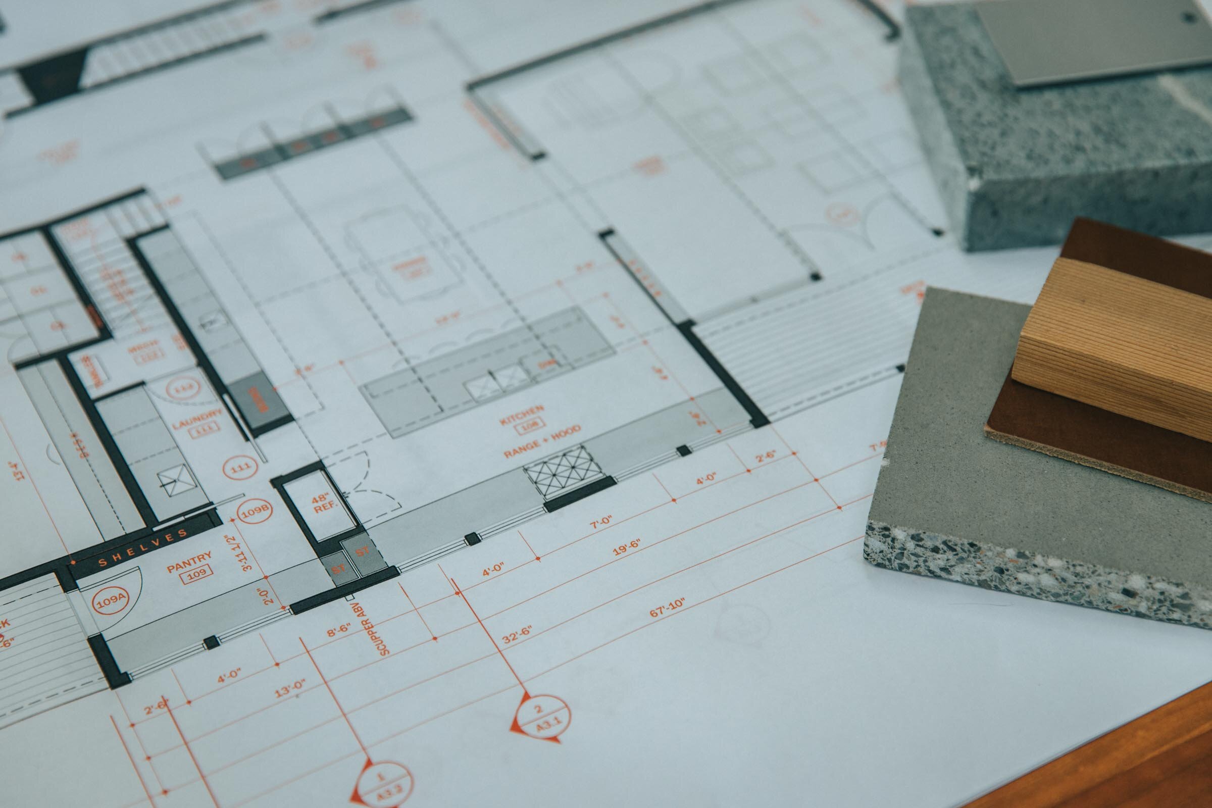
In this architectural plan drawing tutorial I'll walk you through the exact settings, line weights, pen styles and layers I use to develop digital architectural drawings for my residential architecture do. We'll focus on how to recreate the floor program yous run across in the thumbnail prototype below. You'll also learn how architects choose what to draw, how we approach our drawings conceptually, and how we organize information.
I employ AutoCAD for all my drawing work right now, only yous tin do this with any tool y'all have on hand: pen, pencil, Revit, another BIM software, whatever y'all cull. Tools don't make the drawing, you practise. I use probably the almost primitive grade of CAD in that location is, Autocad LT; so that's proof in itself that y'all don't demand multiple yard dollar BIM software to make nice drawings. Employ whatever tools you have bachelor.
An architect'due south job is to social club things and this certainly extends to our drawings too. There's the organization of the linework on the folio - the layout of the canvass - and there'due south also the club of information that you're depicting - the overall drawing hierarchy. Each requires that you know exactly what yous're trying to communicate. Now, I want to go on this simple for this tutorial so I'll really just be going over how I depict floor plans merely the principles apply to all the different types of drawings. The goal of a flooring plan is to show the relationship of the spaces to i another, all the concrete features of the interior and exterior spaces and to precisely depict the real dimensions of those relationships. It also serves equally a sort of overall map to bear witness the team of tradespeople – the ones you lot're relying on to construct your architecture - where to look for supplemental information. And so it'due south naturally a diagram; nosotros tin't prove everything, we take to decide but what'due south important and leave out the remainder.
A floor plan is an overhead view of a horizontal cut through the building unremarkably taken at 4' above the floor level and of course, it's fatigued to scale. Then, the starting time ordering principle is that the things yous're cutting through – primarily the walls – should always be the heaviest lines on the page. So primal concept number one has to practise with lineweight, and if that'south a confusing term bank check the video in the cards for another tutorial where I describe exactly what that is and its importance.
These drawings look this way because there's a stiff contrast between lineweight the very thin lines and the very thick ones. In CAD when nosotros're drawing we draw on different layers. Each layer is transparent and they stack together to form the cartoon. You can control what you encounter and what you don't by turning layers on and off. Separating things into layers allows us to modify our lineweights – among other things – to quickly change what'south being depicted as heavy and what's not. The process of design involves many changes, so keeping things organized on split up layers volition allow you to change things efficiently. Now, I like to keep things ultra-simple and for this exercise particularly: I set up my layer groups past lineweight, that's all. Some architects and consultants utilise hundreds of layers and I suppose in some cases it makes sense assuming you lot demand that level of control, just I recommend starting with only a few. Mine are in a template file that I use to start new drawings and they're described very simply: from heavy all the manner to superfine. I as well take a few additional layers which are helpful: one is for annotations – things similar text, dimensions and detail bubbles, one for subconscious lines – to show something above or below and then 1 for hatch patterns. I can turn off whatever of the layers I don't demand, so I can work more chop-chop or in a less-chaotic surround. So, you lot may need more or less depending on the blazon of work you practice, but this is a prissy simple place to beginning. Any heavy lines you want to draw, y'all'll put on the heavy layer, very thin ones on the superfine and and so forth. In this way, information technology's a bulletproof organisation for forcing yous to pay attention to lineweight, which is – I think - the near important affair in making your drawings graphically convincing.
My CAD program is setup to impress these lines co-ordinate to their color and color is assigned by layer. And then if I'g drawing on the heavy layer, the line is e'er white and white always corresponds with a certain line thickness. Brand sense? White is always associated with a sure thickness which is fix in - what Autocad calls - the color table. But all of that is not really important, because whether or not you're non using Autocad you lot can simply modify the thickness of the line. In Autocad I employ polylines to change thickness but there are other ways even in autocad and your software might call it something altogether different. Past changing thickness, this adds even more control over how much dial your drawing has and what's nice is that it's conspicuously visible on the screen as having a heavier lineweight. Now, if yous showtime making really thick lines everywhere just capeesh the fact that when you lot modify the calibration yous're printing your drawing at, the lines will look thicker or thinner so only be enlightened of that. For the quarter inch scale residential floor plans I'k drawing here, I like to draw the outer edges of the exterior walls on the heavy layer and add a little extra punch by using a 1" thick polyline. If you make a template drawing with a variety of thicknesses in it, you tin can arrange to whatever scale you lot're printing or working at. If you're drawing past hand, lay your walls out showtime, then come back after and add a heavier outline with a softer lead or darker pen.
To get into the nitty gritty, on the flooring plan drawing, outside walls are assigned to the heavy layer and I prove them every bit a 1" thick polyline as I said. The medium layer is very shut to the heavy one in weight and and so I use it for accenting things like the top risers of stairs, or site retaining walls, or site bedrock groupings. I use the 'light' layer for floor edges, door slabs, window frames, counters, cabinetry, and plumbing fixtures, while door swings and window sills I put on the superfine layer. Likewise on the 'superfine' layer I put all the wall sub-assemblies, things like stud framing lines or substrates similar plywood sheathing or tile capitalist. But, more than on this before long. Article of furniture is fatigued on the extra-fine layer, floor hatches on the hatch layer, cabinets and counters are hatched differently depending on how alpine they are too. Overhead lines are on the 'hidden' layer and text and annotations are on the 'text' layer, again more on this in a minute.

The adjacent central concept is to use screening. Now, I'thousand not talking about hatches per se hither, simply using screened pen weights. I employ everything from a 10% screen all the way up to an 80% screen. In my colour table - the file that tells my printer what to print - I've assigned the colors 201 – 208 dissimilar corresponding screened pen weights. And then, annihilation assigned color 201 prints as a 10% screen, 202 is xx% and and then on. And, you tin can apply this to your thick lines for fifty-fifty more control over how something looks and for fifty-fifty more diversity, you lot might modify the linetype too. Take a 1" thick line and assign it the 201 colour and a hidden linetype and now you lot have a thick dashed line with a 10% screen which might be great for showing ventilation runs on a flooring plan for example or use a solid 1 for a handrail or a louver vent in an meridian.
You can also utilize this technique to our side by side key concept which is: using hatches to add depth and item. Hatches are basically patterns that infill sure boundaries in your cartoon, they can exist made up of tiny dots, shapes, crisscrossing lines or nuance-dot lines, or – my personal favorite - solids. When you start using hatches along with the screened pen weights, you lot have nearly infinite options for creating depth and subtlety in your drawings.
I use hatches to shade in the outside walls – what architects telephone call poche – in this drawing it's an 80% screen on a solid hatch and then color 208 on the hatch layer. I employ hatches to indicate materials: like wood flooring, concrete block or tile patterns and I also apply them for shade and shadow to call attending to something of import in the drawing. On flooring plans I utilise a variety of scales of dot pattern hatches on say descending stairs or as angled lines to testify a partial tiptop wall or cabinetry or a countertop surface. I besides utilise solid screened hatches on all my glazed surfaces on outside elevations, from between 40 and threescore% screening. I use them in for the tree backgrounds likewise the ones you see here in the summit drawings. I basically utilize them everywhere I tin because they help call attention to things that are important and they add a softness to the cartoon that I call back looks I don't know, painterly I guess.
Scale elements: By adding furniture, scale figures, cars, trees and other elements to signal scale yous'll introduce a existent sense that your architecture is meant to be inhabited. Doing this too ensures you're accommodating the regular elements your end users will need to functionally use the architecture also. Knowing your customer wants to use an 8' sofa will help you locate the floor outlets nearby and ensure information technology's not obstructing a door swing.

When you're drawing plans it's adept to begin thinking most materials and systems too. Information technology's okay if you lot're missing this information early on and you're working on conceptual plans, but I like to begin with at least some idea of how I'll be constructing the building. For case, is it a masonry exterior? Is in that location a glass curtain wall? Concrete, forest framed walls, finishes, each of these materials has a thickness and when you start to plough corners and add together jogs or if you begin intersecting different buildings or surfaces, knowing what those materials are becomes really important when yous're cartoon.
Your concluding floor plan drawing can exist as general or as detailed as yous'd like, but the more detail you imbue your cartoon with, the more than useful a tool it volition be later on when you lot're drawing cavalcade details or figuring out how the glazed wall meets the concrete retaining wall. When I begin cartoon a programme, I choose a wall thickness and some basic finishes equally a starting point. So here I started by laying out the outside face of the stud wall on the superfine layer. For our squid cove project nosotros actually started with a double 2x4 stud wall on the exterior spaced apart to prevent thermal bridging. So I commencement the outer perimeter by 3 and a half inches the width of a 2x4 wall, and and then a quarter inch for the pause, so some other three and a half for the inner stud wall. Then I offset the interior finish thickness of ½" for the gypsum wallboard, and then on the outside i/2" for the exterior capsule and another inch for the exterior shingled walls, At present, forth the way, every bit the pricing came back for the double 2x4 wall system it was a lot more expensive than we anticipated so we had to change information technology back to 2x6 walls. Now, considering windows have a long time to fabricate, this modify actually happened after our windows had been ordered and so those openings were fixed on the plan, we had to utilize those openings. So, we were left with this detail at the interior corners to resolve. Knowing the actual systems and sizes of everything around them immune us to design the trim effectually the windows that not only matched the detailing on the residual of the project only fabricated it look like it was an intentional design conclusion. So when you can, show finishes. They also fill in this fine layer of linework that makes the contrast between thick and thin actually popular.
Lastly, sort of the icing on the cake, we have the annotations. Annotations round out the information you're conveying on the plan. They're actually important wayfinding tools for the contractor so they need exist very clearly organized. I use red text to arrive clear that the annotations are a function of another ordering organisation and also something they need to pay attention to. And, the ink is only pennies more than to print them in colour, honestly…I call back it's so worth it. You lot could go far blue or greyness too, whatever you lot choose. I like the red because information technology's piece of cake to point to a note and say, information technology's noted in ruby-red, hard to miss, right? This works in both directions by the mode, and so if information technology's your mistake it'll be pretty credible! Annotations describe things y'all're non able to draw, they reference other drawings and details, and should all exist on the 'text' layer so you lot can turn them on and off as needed for presentation or while you're making other changes to the programme. Annotations grow over time, they'll be bones at outset things like room labels and they'll get progressively more than numerous every bit y'all make blueprint decisions. Now, I'g begging you please…please, please…don't use those mitt-lettered fonts…just uninstall those from your computer. I use Franklin Gothic for mine, only anything just the chiseled pseudo-hand lettering should be fine.
You'll know you've washed this all correctly when you squint your eyes and you tin can easily see what's of import. Exercise the walls stand out? Do the annotations fade. Every bit you spend more time looking for data, more information should become apparent, almost like a pull focus or deadening reveal. Calorie-free lines of the hatches should be the first to fade and last to come into focus.
So that'south information technology, I hope information technology was helpful!
If yous want my template, there are 2 versions available:
AutoCAD template
Revit template
Source: https://thirtybyforty.com/blog/architectural-drawing-tutorial-how-i-draw-floor-plans
0 Response to "The Process of Drawing Architectural Plans"
Post a Comment